One of the most successful Bluetooth Low Energy devices that started appearing in our Smart Home is the Xiaomi Mi Flora. Decoded and integrated into OpenMQTTGateway in 2017 this device enabled us to have a nice follow-up on our plants and vegetables' health.
One of the main drawbacks is its power consumption, I'm around 6-9 months in terms of battery life. Not very satisfying when we see BLE sensors that can last several years.
By chance, I found recently the work of Raphael about the b-Parasite, a BLE open-source plant sensor: https://github.com/rbaron/b-parasite
It is interesting from several aspects:
- Nice form factor and size
- The moisture probe is integrated into the PCB
- You can order directly from the files proposed to a PCB manufacturer with most of the components already soldered
- nRF52 powered, a reference module in Bluetooth Low Energy
- It's open-source design and code!


- Black Magic Probe
- Jtag Cable
- JTAG/SWD 0.1in Breakout Adapter
- B parasite soldered
Follow this tutorial so as to set up your environment:
Once done clone the Github repository for the b-parasite:
https://github.com/rbaron/b-parasite
Building and flashing
- Go to the code/b-parasite folder
- Build with the following command:
$SDK_ROOT=/Applications/nRF5_SDK_17.1.0_ddde560 make
Compiling file: main.c
Compiling file: adc.c
Compiling file: ble.c
Compiling file: pwm.c
Compiling file: rtc.c
Compiling file: shtc3.c
Linking target: _build/nrf52840_xxaa.out
text data bss dec hex filename
34540 252 3148 37940 9434 _build/nrf52840_xxaa.out
Preparing: _build/nrf52840_xxaa.hex
Preparing: _build/nrf52840_xxaa.bin
DONE nrf52840_xxaa
- Go to the _build folder and ls
$ cd _build
$ ls
nrf52840_xxaa nrf52840_xxaa.map out_300.hex
nrf52840_xxaa.bin nrf52840_xxaa.out out_sleep-adv.hex
nrf52840_xxaa.hex nrf52840_xxaa_300.hex s140_nrf52_7.2.0_softdevice.hex
nrf52840_xxaa.in out_1.hex
- Copy the softdevice for nrf52840 downloaded in the prerequisites into the _build folder
- Merge the program with the softdevice
$mergehex -m s140_nrf52_7.2.0_softdevice.hex nrf52840_xxaa.hex -o out_sleep-adv_300.hex
Parsing input files.
Merging file "s140_nrf52_7.2.0_softdevice.hex" into output.
Merging file "nrf52840_xxaa.hex" into output.
Storing merged file.
- Connect the Black Magic Probe to the B-Parasite (without battery) and with the JTag 7 pins adapter
- Adapter VCC to B-Parasite VCC
- Adapter GND to B-Parasite GND
- Adapter TCK to B-Parasite CLK
- Adapter TMS to B-Parasite IO
- Launch the command below to identify the interface to use
$ ls /dev | grep 'modem'
cu.usbmodem98B699941
cu.usbmodem98B699943
tty.usbmodem98B699941
tty.usbmodem98B699943
- Launch gdb
$ arm-none-eabi-gdb
- Select target
(gdb) target extended-remote /dev/cu.usbmodem98B699941
Remote debugging using /dev/cu.usbmodem98B699941
- Power the nRF52
(gdb) monitor tpwr enable
Enabling target power
- Scan targets
(gdb) monitor swdp_scan
Target voltage: 3.3V
Available Targets:
No. Att Driver
1 Nordic nRF52 M4
2 Nordic nRF52 Access Port
- Attach target 1
(gdb) attach 1
Attaching to Remote target
- Upoad firmware
(gdb) load out.hex
Loading section .sec1, size 0xb00 lma 0x0
Loading section .sec2, size 0xf000 lma 0x1000
Loading section .sec3, size 0x10000 lma 0x10000
Loading section .sec4, size 0x6634 lma 0x20000
Loading section .sec5, size 0x8818 lma 0x27000
Start address 0x00000000, load size 190796
Transfer rate: 34 KB/sec, 973 bytes/write.
- Launch debug
(gdb) run
The program being debugged has been started already.
Start it from the beginning? (y or n) y
Starting program:
warning: No executable has been specified and target does not support
determining executable automatically. Try using the "file" command.
And that's it, the program is loaded, so now, how to verify that this is working?
The b-parasite can advertise its data following different protocols, you can choose it here.
The default protocol is supported by OpenMQTTGateway and Theengs Gateway out of the box. So you can either web upload an ESP32 with OpenMQTTGateway (choose esp32dev-ble-cont for continuous scanning), install Theengs gateway on a server, or Theengs Gateway as an Addon in Home Assistant (for the server installtations reduce the time between scan to 0 so as to have continuous scanning).
Once done, connect to the MQTT broker and you should be able to see the data coming like below:
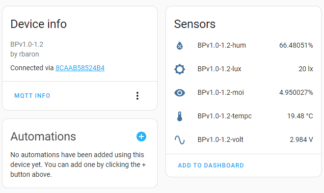
{ "id":"F0:CA:F0:CA:01:01", "mac_type":1, "name":"prst", "rssi":-89, "servicedata":"21000ba8079caa300cacf0caf0ca01010014", "servicedatauuid":"0x181a", "brand":"rbaron", "model":"b-parasite", "model_id":"BPv1.0-1.2", "tempc":19.48, "tempf":67.064, "hum":66.48051, "moi":4.950027, "lux":20, "volt":2.984 }
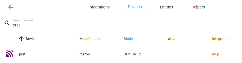
With Home Assistant you will have directly the sensor auto-discovered and display values like below:

Commentaires
Enregistrer un commentaire